Though power supply circuits are very common in electronic books and on internet yet I found it necessary to discuss it here in the simplest possible way that can easily be understood by new electronic enthusiasm. Power supply of different kind is needed to carry out test on your design or project either bread-boarding or finished work. It can also be used to power some of your household appliances.
There are two types of electrical power. These are alternating current (AC) and direct current (DC). From here I will be referring them as AC and DC accordingly.
Alternating Current (AC)
Pure sinusoidal AC voltage is produced from AC generator called alternator. You may have heard wind powered generator, petrol or diesel generator, gas turbine, thermal turbine or hydro turbine; all these have electrical part which is an alternator. Other part or every other components attached are to drive or cause the alternator to rotate in order to produce electricity (AC voltage). This is called AC because it has both negative and positive halves that alternate at every half cycle.
Direct Current (DC)
On like AC, there are three main sources of DC voltage. These are DC generator (only difference between AC and DC generators is presence slip rings in AC generator and split rings in DC generator), chemical (battery: wet or dry cell) and solar (photovoltaic module). How DC generator, battery or photovoltaic module convert mechanical, chemical or solar energy respectively to electrical energy will not be discussed as it is not within the scope of this topic.
Though I have mentioned three main sources of DC voltage, yet DC voltage can also be derived from AC source with the aid of rectifier circuit. Inside your radio set, CD player, PC power pack there is atleast a rectifier circuit that converts AC voltage from your power outlet to DC voltage; that is the reason you are able to plug them in to AC power outlet.
The process of converting AC voltage to DC is called rectification while the circuit that performs the task is called rectifier circuit. A rectifier circuit could just be a diode/thyristor or network of diodes/thyristors. Aside rectifier, you may also need transformer in your system depending on the voltage level of the AC source and your desired DC voltage.
How diode works
It is very important we look at 'how diode works' before we go to 'how rectifier works'. A diode is an electrical device that allows current to flow in only one direction. See below diode circuits (a) and (b) where diode in circuit (a) is forward biased while diode in circuit (b) is reverse biased. Anode of diode in (a) is at higher potential relative to its cathode and hence allows current to flow. In (b) cathode of the diode is at higher potential relative to its anode, hence it blocks the flow of current. Having understood 'how diode works', let us go to 'how rectifier works'.
How rectifier works
Half wave rectification
Below is a half wave rectifier circuit which makes up of a single diode for the purpose of rectification. During the positive half cycle, anode of the diode is at higher potential relative to the cathode while cathode is at higher potential relative to anode during the negative half cycle. All positive half waves are permitted while the negative half waves are blocked. This results to the wave shown in the figure below.
Full wave rectification
Below is a full wave rectifier circuit which makes up of four diodes network for the purpose of rectification.
During the positive half cycle, point A of the AC power source is at higher potential hence current flows through diode D2, the load, D3 and back to the source through point B as illustrated with figure (a) below. During the negative half cycle, point B of the source is at higher potential hence current flows through D4, the load, D1 and back to the source through point A as illustrated with figure (b). I want you to note the direction through which current flows to the load in both halves. This shows that the source has been converted to DC as it flows through the load in one direction.
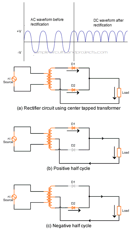
Full wave rectification using center tapped transformer
I believe the following figures should give you the clear picture of how rectification is done in this type of rectification circuit.
Without dwelling too much on rectification, let us quickly look at how to smoothen output of rectifier.
Rectifier with filter capacitor
In the rectifier circuits discussed above, outputs in all the cases are pulsative DC voltage. In almost all applications, smooth and non-pulsative DC is most desired. This leads to introduction of filter capacitor to filter out the pulses. See the figures below for what the wave forms look like after introduction of filter capacitor C.
Even with the introduction of the capacitor, undesired element (ripples) which depend on the applied load still exist. To get rid of these ripples, many voltage regulator ICs have been developed so as to have a smooth DC voltage. Some of these ICs are LM317 (variable output voltage), LM7812 (+ve 12V), LM7912 (-ve 12V), LM7806 (+ve 6V) and soon on.


no referance
ReplyDelete